
Wiring Diagram For A Brake Controller
A wiring diagram for a brake controller is used to guide the installation and troubleshooting of a device that transfers electricity from the vehicle's battery to the brake calipers. When it comes to understanding the wiring diagram for a brake controller, the first thing to understand is the different kinds of wiring diagrams.
Brake Motor Wiring Diagram
The brake controller wiring diagram is the basis for all your braking system's operations, and it's important to understand how it works. It's a schematic representation of the entire braking system, showing each of the components and how they interact with one another.

Flat Four Wiring Diagram Brake wiring diagram creator
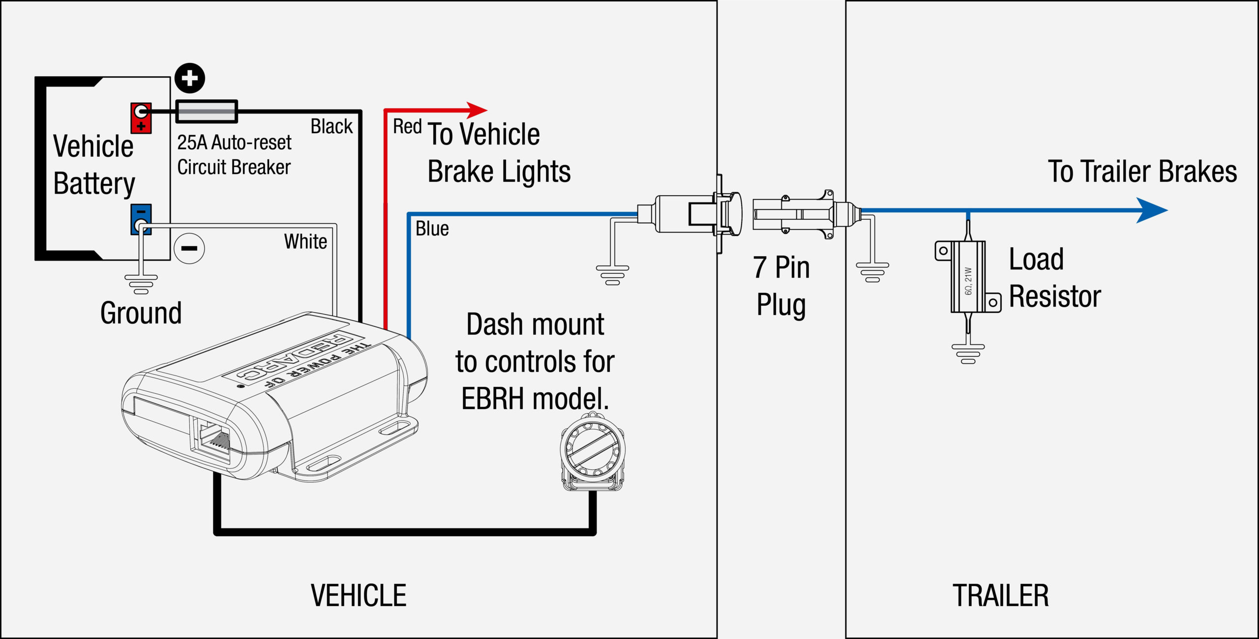
Page 8: Wiring Diagrams INSTALLATION 2.2.2 Wiring Diagrams 25A Fuse or INPUT 30A Circuit Breaker (CBK30-EB) To 12V Trailer 3.0mm² Blue 3.0mm² 12V Vehicle Brakes Black Start Battery To 12V Vehicle 1.25mm² Brake Light trigger Ground (refer to section 2.2.1) 1.25mm² White Dash mount controls for Tow-pro. Page 9: Mounting The Remote Head

Curt Discovery Brake Controller Wiring Diagram S0456
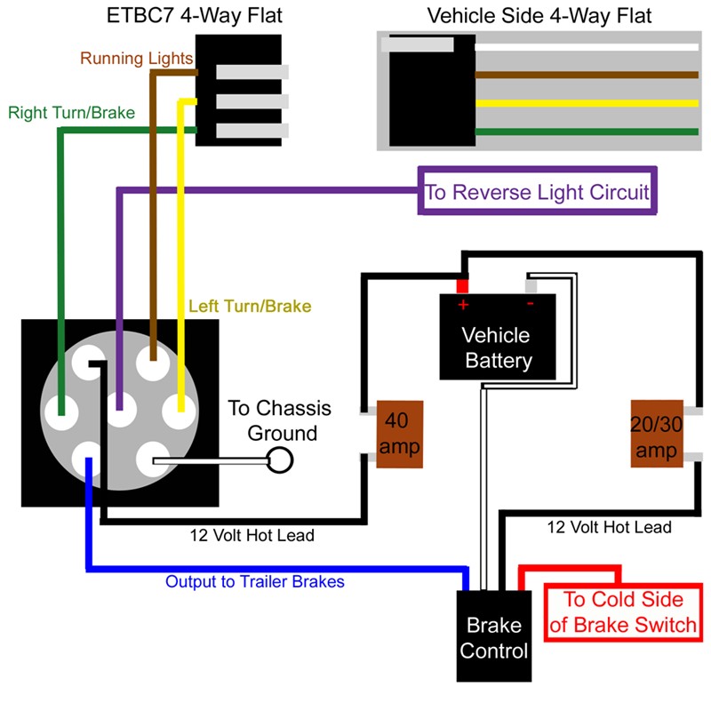
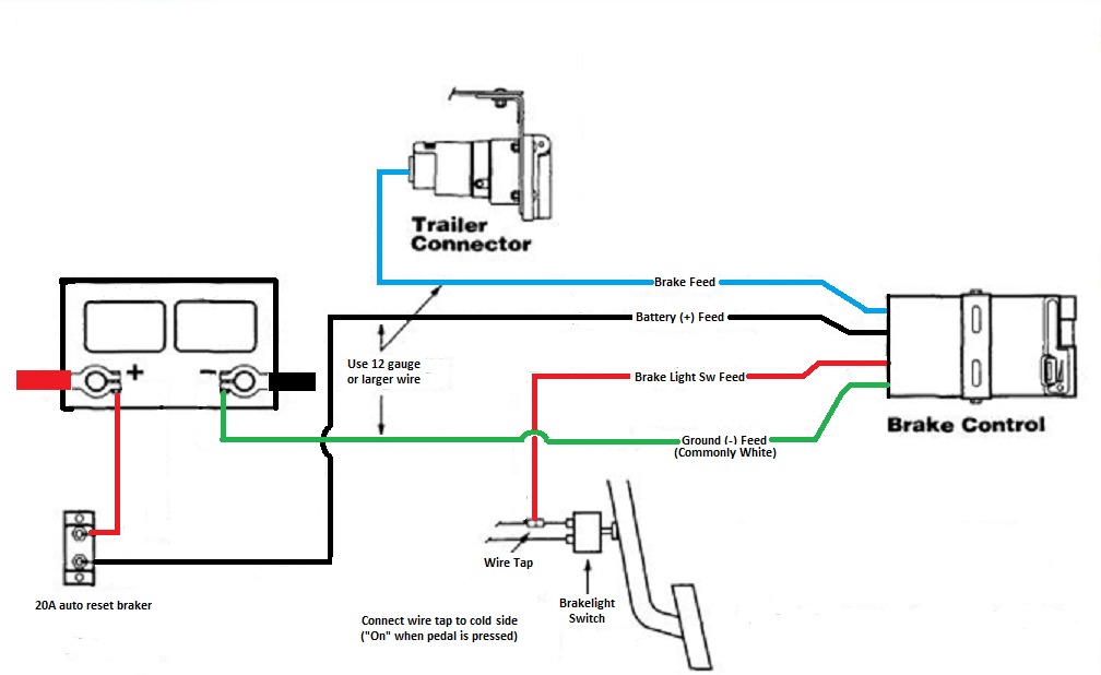
The BLACK wire is the power supply line to the brake control. 4. The RED (stoplight) wire must be connected to the cold side of the brake pedal stoplight switch. Splice down line from the switch; DO NOT disturb the position of the switch. 5. The BLUE (brake output) wire must be connected to the trailer connector's brake wire.
Electric Brake Wiring Diagram Breakaway
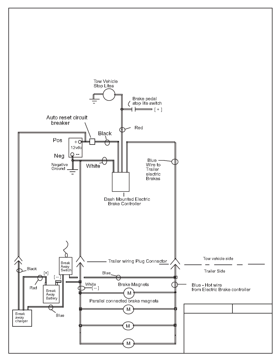
bRake contRols - tecHnIcal Wiring instructions For ElEctronic BrakE controls generic Wiring Diagram STOPLIGHT SWITCH - CONNECT TO COLD SIDE (VOLTAGE ONLY WHEN PEDAL IS PUSHED) SPECIAL INSTRUCTION FOR 1989-91 FORD E AND F SERIES TRUCKS AND VANS WITH ANTI-LOCK BRAKES - DO NOT CONNECT TO STOPLIGHT SWITCH ON THESE VEHICLES LIGHT GREEN WIRE
Pj Trailer Electric Brake Wiring Diagram
A brake controller wiring diagram will typically include the following components: Power Source: The power source is the battery or other source of power required to run the brake controller. Controller: The controller is the main part of the system, providing the means to adjust the braking force.
Electric Trailer Brake Wiring Diagrams
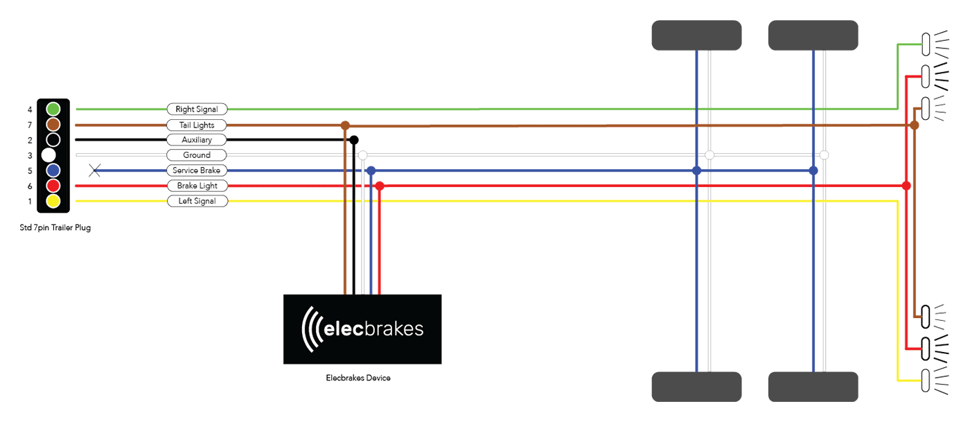
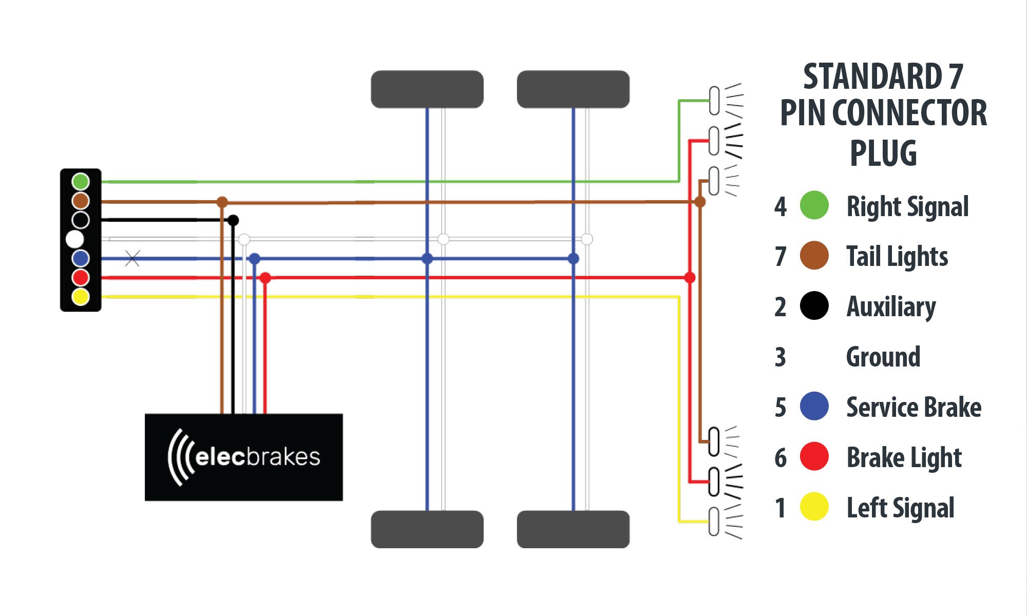
The following diagram is a general guide for wiring common brake controllers into cars. Please ensure you have the correct gauge wire and we do recommend you use an auto-electrician to wire the brake controller into your car.
Wiring A Brake Controller
In that case the device would be configured as per the following electric brake controller wiring diagram. For more information on how electric brake controller option using our hard-wired option, see our handy installation guide. 3. Connect Device using smartphone app.

Trailer Brake Controller And Wiring Kit
The three basic wiring functions are for tail lights, stop lights and turn signals. NOTE: This 4-pole installation is vehicle specific. If your vehicle does not already have its own 4-pole trailer connector, use the Wiring Fitguide to find the harness recommended for your vehicle. The Colors of the Remaining Four Wires:
Air Over Electric Trailer Brake Controller Wiring Diagram design
Brake Controller Wiring + Diagram Overview metaspencer 57.8K subscribers Subscribe Subscribed 325 Share 33K views 3 years ago #brakecontroller #dumptrailers Bumper-to-bumper overview of the.
Ford Trailer Brake Controller Wiring Diagram Collection Wiring
The electric brake controller wiring diagram consists of various components and connections that need to be properly understood. These components include the power source, the brake switch, the brake controller unit, the trailer brake connector, and the trailer brakes themselves. Each component plays a specific role in the overall brake system.

Colorfed Reese Pod Brake Controller Wiring Diagram
Brake Controllers Wiring Guides Wiring Guides Hard wiring a Tow-Pro How to charge a Brake-Away system with an Electric Trailer Brake Adaptor Why is a wiring kit is required when installing a Tow-Pro in a Ford vehicle? Rugged, adventure proof gear. Exploration without limits. Power that won't let you down. Phone Tech Support Line: 1300 733 272
Trailer Brake Controller Wiring Diagram Cadician's Blog
What is a Wiring Diagram Electric Brake Controller? A wiring diagram electric brake controller is a diagram that diagrams the wiring of the electric brake controller. This diagram will show you the connections between the various components that make up the controller.
Travel Trailer Brake Wiring Diagram
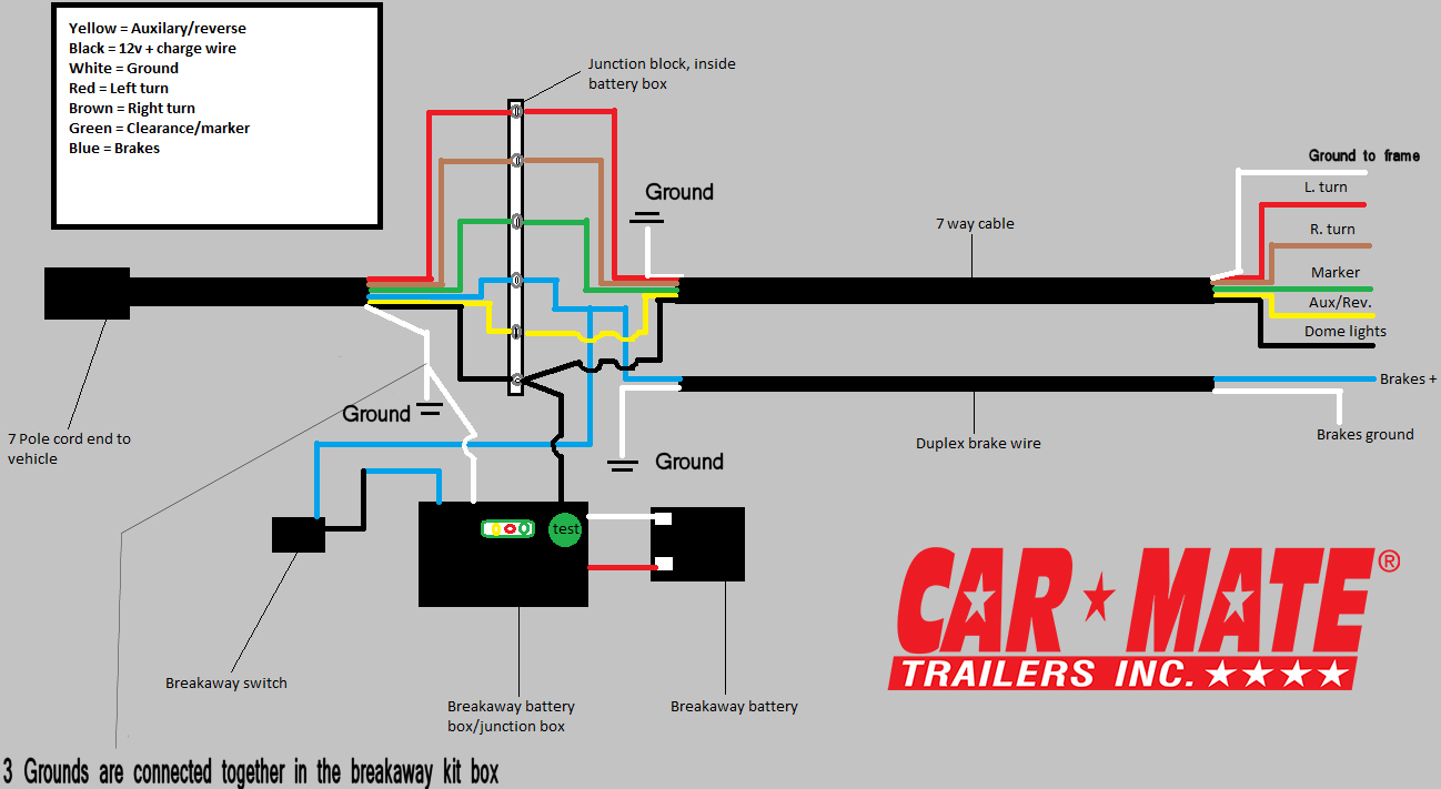
The wire needed is the light green wire, second from the end in the outside row of seven wires (see the box shown in wiring the diagram). Splice the brake control brake control's red wire to light green wire using a wire tap. Using 10 gauge stranded wire and ring terminals, connect the "BATT" side of the circuit breaker to the positive battery.
Hopkins Agility Brake Controller Wiring Diagram For 2007 Dodge Ram 1500
The brake motor wiring diagram provides a visual representation of how the different components of the motor and braking system are connected. This diagram includes information on the wiring of the power supply, motor, and brake control circuit. It also shows the connection between the motor's magnetic brake and the braking control unit.
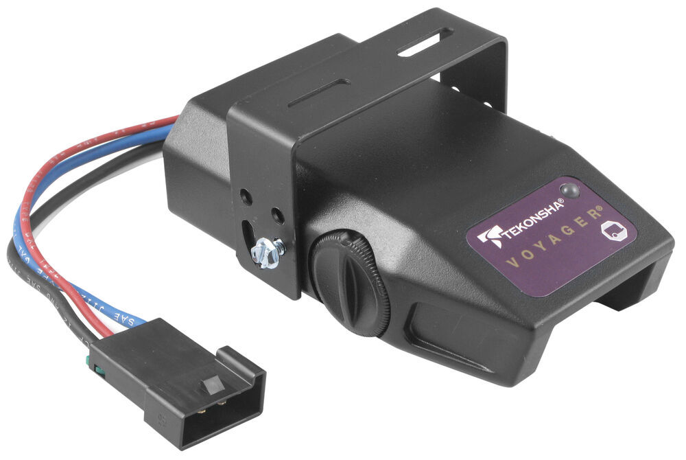
Wiring Diagram For A Tekonsha Trailer Brake Controller Collection
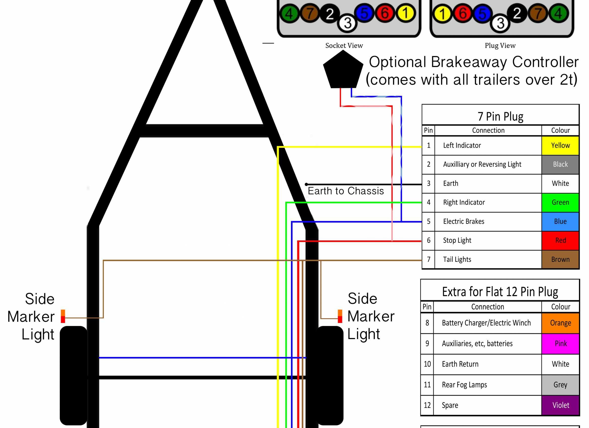
A wiring diagram for a brake controller is an essential tool when it comes to installing, troubleshooting, or replacing a brake controller. It should show all connections and components, such as the brake switch, the trailer brakes, and the trailer connector. It should also accurately depict the polarity of each connection.
