
Square D Gfci Breaker Wiring Diagram Free Wiring Diagram
Cut the wire to length so that 20cm (8") sticks out of the outlet box, and about 80cm (30") sticks out at the electrical panel. [4] 7. Cut about 15cm (6") of the (usually yellow or gray) outer jacket away from the wire, being careful to not damage the inner black or white jackets.
220 Volt Breaker Wiring Diagram
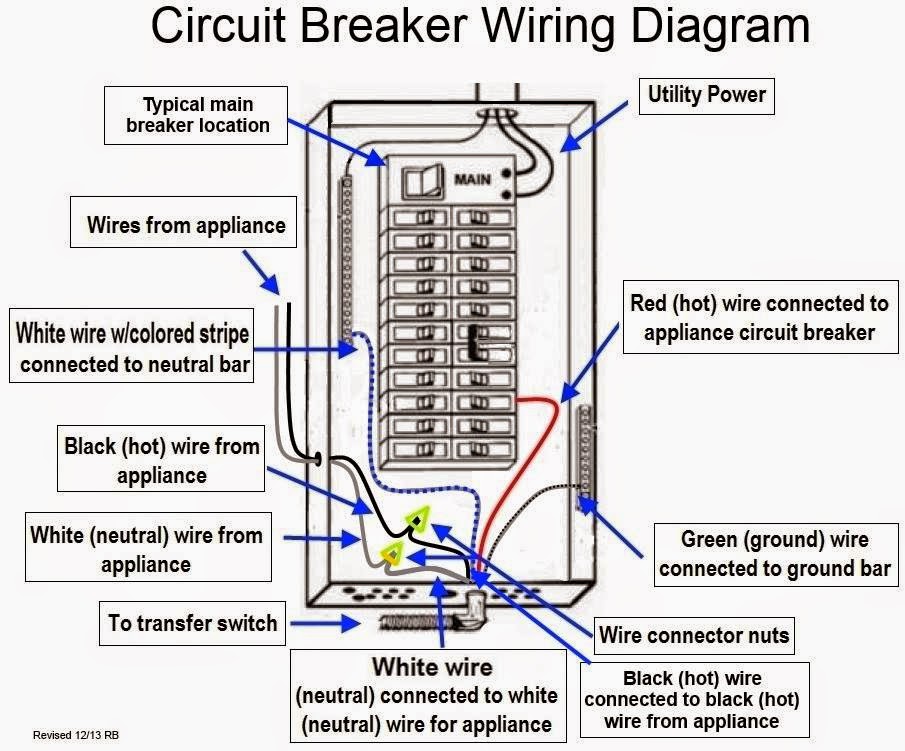
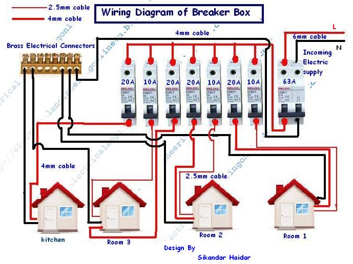
The wiring diagram of a circuit breaker panel shows how all the electrical components are connected and how the power flow is distributed. It includes the main breaker, which controls the power supply to the entire panel, and individual circuit breakers that control power to specific circuits or appliances.

electrical Using a 30amp tandem circuit breaker for a 120/240v
This page contains wiring diagrams for a service panel breaker box and circuit breakers including: 15amp, 20amp, 30amp, and 50amp as well as a GFCI breaker and an isolated ground circuit. Circuit Breaker Panel Box Wiring Diagram This diagram illustrates some of the most common circuits found in a typical 200 amp circuit breaker service panel box.

Square D Gfci Breaker Wiring Diagram Free Wiring Diagram
1 Plan the Circuit To wire a new circuit, identify an open slot in your breaker box for a new circuit breaker. Work during the daytime as you will need to shut off all power in your home during most of the project. Measure the room or rooms where you'll be installing the new branch circuit, and draw a detailed, accurate floor plan.

Simple Circuit Breaker Diagram
$51-100 Introduction Adding a new circuit can be a daunting and even dangerous job. We show you how to do it with step-by-step instructions and important, life-saving safety tips. Tools Required Flashlight Needle-nose pliers Pliers Utility knife Voltage tester Wire stripper/cutter Materials Required AFCI circuit breaker Cable clamp
29 Circuit Breaker Box Diagram Wire Diagram Source Information
A schematic diagram is a drawing that shows electrical system circuitry with symbols that depict electrical devices and lines representing conductors. Only qualified persons should review schematic diagrams and perform work on circuit breakers.

585 best images about Electrical circuits,wiring,motors, install and
With the appropriate 10 gauge wire, the right breaker, and a compatible receptacle, installing a 30 amp breaker and its circuit can be your DIY project. Follow this guide for more details. Table of Contents.. Check the wiring diagram when wiring a 30 amp receptacle. A 10-3 cable for 240 volts will have two hot wires, one neutral, and one.
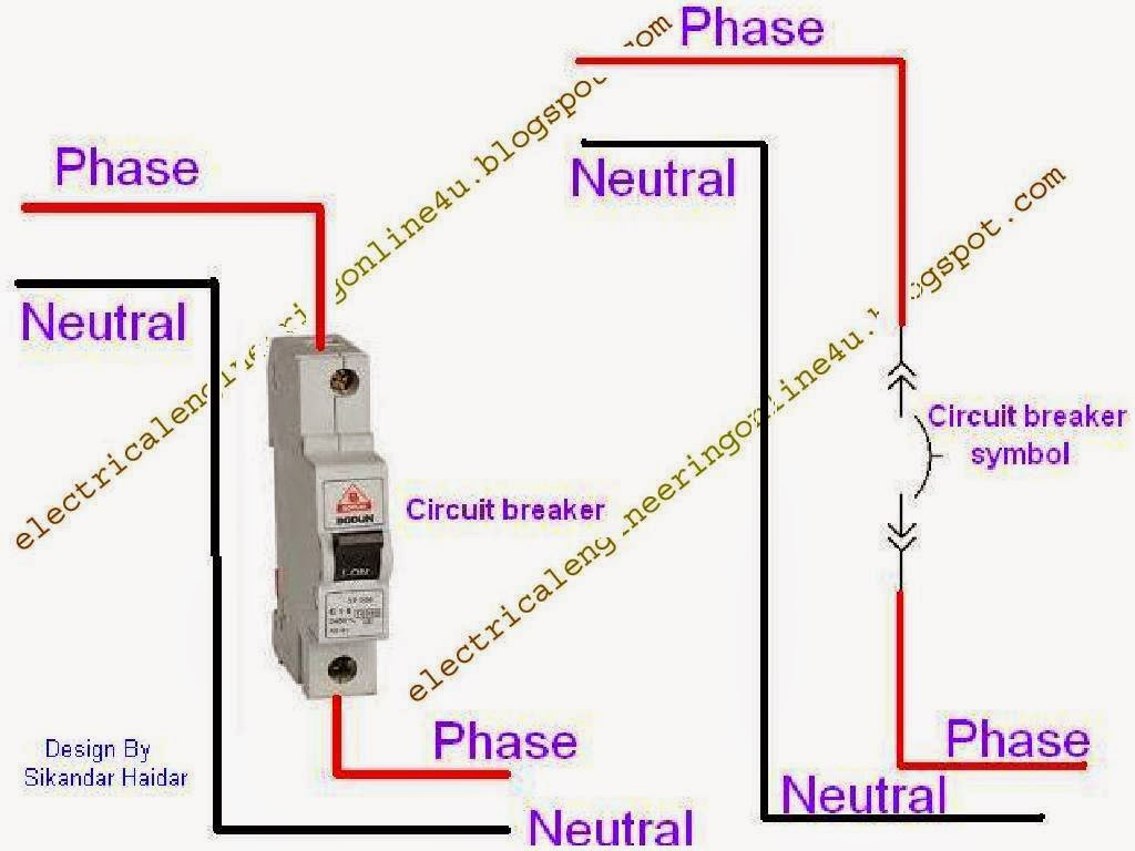
How To Wire A Circuit Breaker Electrical Online 4u
The Spruce / Kevin Norris. One 15- to 20-circuit breaker box. $700 to $950 (labor not included) This overview describes how a professional electrician connects a residential electrical circuit breaker panel to the main service wires coming into the home, and to the individual branch circuits in your home. In almost every situation, this will be.
Simple Circuit Breaker Diagram »
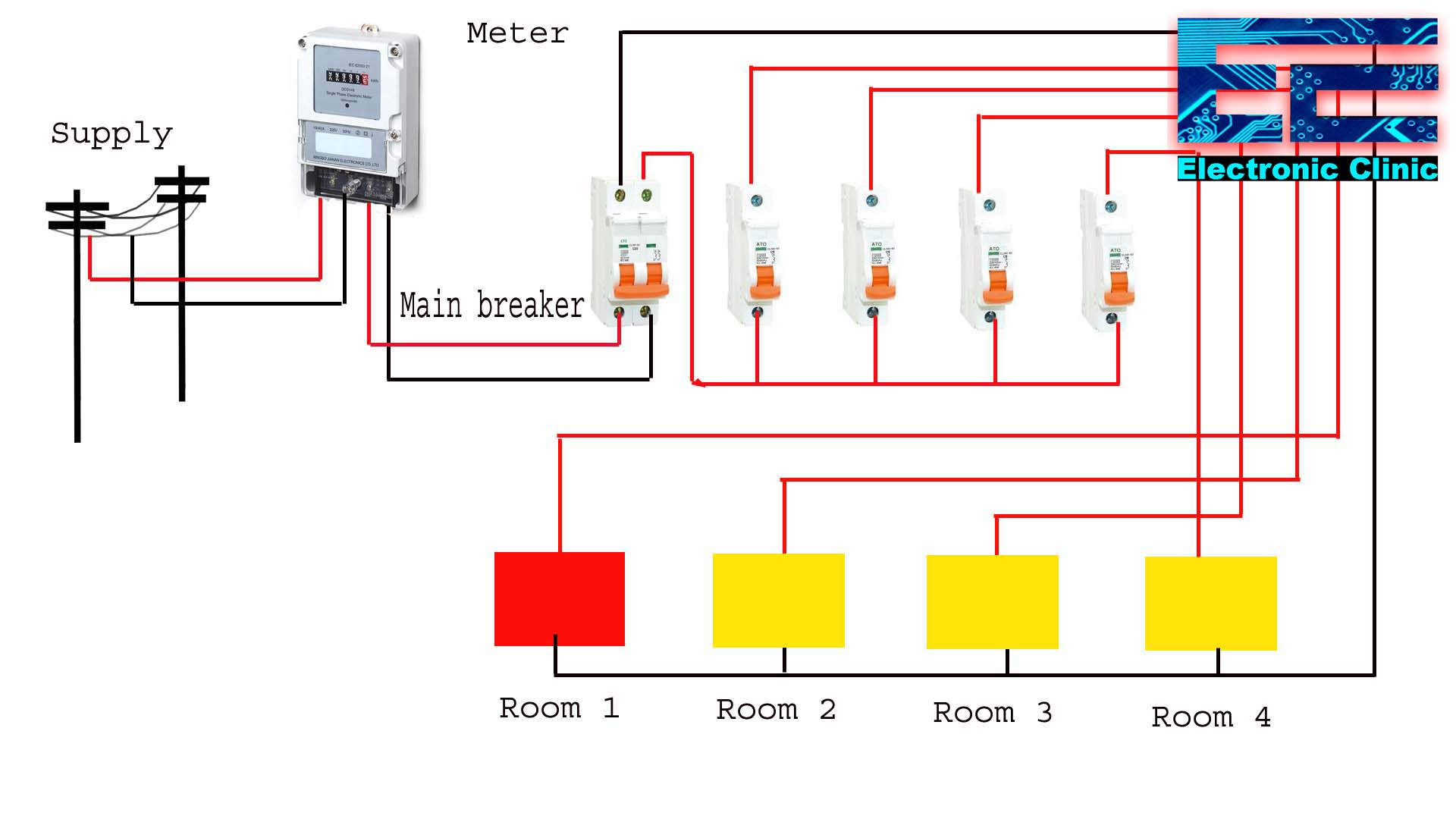
The breaker box, or service panel, operates as a central relay point: It takes power from the street, then feeds that power to the different electrical outlets and hard-wired appliances.
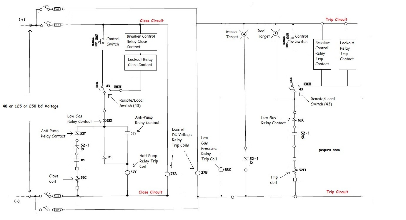
Power Systems Engineering Power Circuit Breaker Operation and
There are three basic types of wiring diagrams: Wiring: Depicts electrical devices as drawings or pictures connected by lines representing wires. Wiring diagrams show specific electrical connections. Pictorial: Shows how components are related to others on the same circuit, but contains less detailed information about electrical connections.

Breaker Wiring Diagram 3 Pole Circuit Breaker Wiring Diagram Download
Chapter Wiring One-and Two-Pole Breakers Follow the guidelines for installing breakers for general-use, lighting, and small-appliance circuits as well as for larger-appliance circuits. By Mike Litchfield, Michael McAlister Installing a Standard One-Pole Breaker
How To Wire And Install A Breaker Box Electrical Online 4u
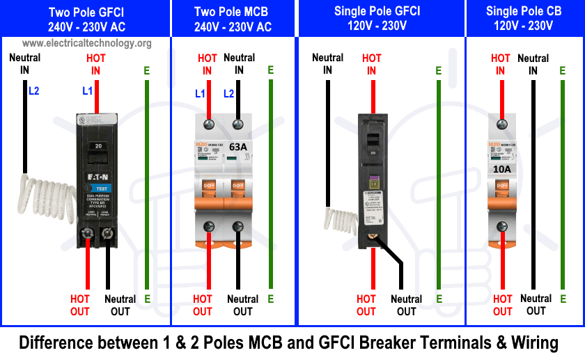
To install a 240V single phase circuit, just mount the 30A two pole circuit breaker in the metal tracks (designated for two hot busbars) which tightly holds the breakers. The two output wires from the circuit breaker connect directly to the load point. Additionally, the bare conductor as ground wire connects to the load point.
afci circuit breaker wiring diagram
Electronic Circuit Breaker - Circuit Diagram, Working and Applications. AC device that we use in our homes generally have a limit to handle the current and voltage. These threshold voltage and current are called the device rating, and are the measurements given by the manufacturers in the range of which the device will work properly.

2 Pole Gfci Breaker Wiring Diagram Free Download Wiring Diagram Schematic
This diagram provides a clear overview of how the breakers, wires, and switches are interconnected, ensuring a safe and efficient electrical system. Whether you're a homeowner looking to understand your home's electrical setup, or an electrician troubleshooting an issue, having a wiring diagram is invaluable.

[DIAGRAM] 20 Double Pole Switch Wiring Diagram Schematic
Keep in mind that the the difference between single pole and two poles normal circuit breakers and a GFCI is that there is a builtin white wire on the back side of GFCI and it must be connected to the neutral busbar in the mains supply or it will not work and protect the circuit properly.

Home Breaker Box Wiring
1 Switch off the main power switch. This should be located at the top of the breaker panel. 2 Take the cover of the breaker box off. 3 Use an electrical tester by putting the tip of one probe against the ground bus bar and the other against one of the screws of a circuit breaker. Connected to this screw should be a red, black, or blue covered wire.
